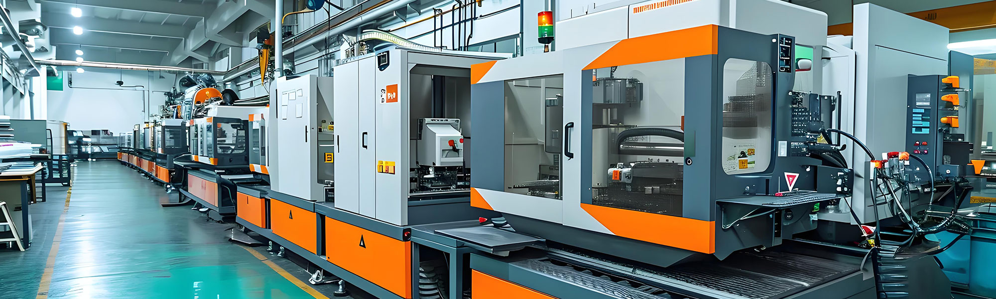
Micro MIM is metal injection molding for parts under 0.2 g, with 0.2–0.5 mm walls and features in the 50–200 µm range. Every process step must be re-tuned, using fine 3–5 µm powder, micro-vented tooling, robotic handling, and optical metrology to hold tolerances.
"Micro MIM" is not a marketing label for small-ish parts. In practice, it describes metal injection molding where the part weighs under 0.2 g, wall sections run 0.2–0.5 mm, and functional features sit in the 50–200 µm range — gear teeth, slots, pivot holes, sealing ribs. At that scale the process is only MIM in its broad strokes: powder, binder, injection, debind, sinter. Every one of those steps has to be re-tuned, because the physics that works comfortably at 20 g quietly stops working at 0.05 g.
The strongest fit today is surgical robotics and minimally invasive instruments. Wrist mechanisms, jaw inserts, clevis links, and cable anchors combine alloy toughness (17-4PH, 316L, titanium) with geometry that would otherwise be machined one at a time from bar stock. A micro MIM tool can produce those features net-shape, in one piece, with no assembly joint to fail during sterilization cycles.
Sensor and micro-actuator hardware is the second cluster: housings, pole pieces, yokes, and counterweights where magnetic alloys such as 50% Fe-Ni or soft magnetic iron are needed in a shape that stamping cannot hold. Orthodontic brackets, hearing-aid components, micro gears for gearmotors, and lock cylinders round out the volume applications.
Ask three questions. First, what is the smallest part they currently run in production, not in a lab sample. Second, which powder grades are stocked at fine particle size, since fine powder supply dictates both lead time and price. Third, how they qualify dimensional capability — a CpK study on the actual feature, not a first-article report alone. Micro MIM is a capability business, not a catalog business. The suppliers who can answer those three questions with data are the ones worth a tooling investment.
Micro MIM typically covers parts weighing under 0.2 g, with wall sections of 0.2–0.5 mm and functional features such as gear teeth, slots, and pivot holes in the 50–200 µm range.
Micro MIM shifts to fine powder with a D50 of 3–5 µm, because a 0.2 mm wall cannot be filled by a 15 µm powder that needs a 1.5 mm flow channel. This raises cost and oxygen pickup risk.
±0.3% on a sintered dimension is realistic, while ±0.01 mm usually means a secondary machining step. Tolerances should be specified per feature, not as a blanket callout.
 Русский
 Español
 Deutsch
 日本語