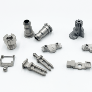
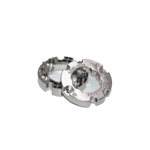
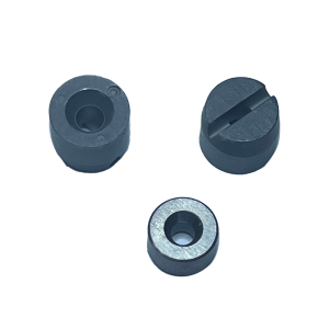
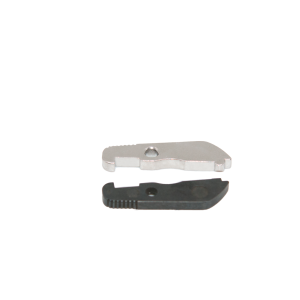
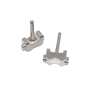
MIM Precision Mechanical Components | Metal Injection Molding Engineering PartsMIM in Mechanical EngineeringMechanical engineering demands parts that move, mesh, lock, pivot, and transmit force — reliably, repeatedly, for millions of cycles. Whether it's a gear tooth carrying torque, a cam lobe controlling a precision sequence, or a linkage arm transferring motion through a kinematic chain, the part must combine geometric complexity with material properties that match the load case. Metal Injection Molding (MIM)is uniquely positioned for mechanical engineering components. It delivers the design freedom of plastic injection molding — complex 3D geometries, undercuts, internal features — but in high-performance engineering alloys that plastic cannot match. The result: net-shape metal parts that replace assemblies of multiple machined components, reduce weight through optimized topology, and achieve production economics that CNC machining cannot touch at volume. At Precision-mim, we specialize in MIM for the mechanical engineering sector — from single prototype gears to multi-million-piece production runs of actuator linkages, all under ISO 9001 quality management. |

|
| Traditional Method | Limitation | MIM Solution |
|---|---|---|
| CNC machining from bar stock | Complex geometry = high cycle time + high cost | Complex geometry = standard molding cycle |
| Investment casting | Surface finish Ra 3.2–6.3µm, limited thin walls | Surface finish Ra 0.8–1.6µm, walls down to 0.3mm |
| Progressive stamping | 2D geometry only, limited materials | Full 3D geometry, full alloy range |
| Powder metal (PM) press-sinter | 88–92% density, 2D compaction | ≥95% density, full 3D molding |
| Plastic injection molding | Low strength, low temperature, creep | Metal strength, metal temperature range, no creep |
| Welded assembly | Labor cost, tolerance stack, stress risers | Single-piece consolidation, no welds |
| Material | Typical Hardness | Tensile Strength | Best For |
|---|---|---|---|
| 17-4PH (H900) | HRC 35–42 | ≥ 950 MPa | General mechanical parts — good strength + corrosion resistance |
| 4140 (Q&T) | HRC 38–45 | ≥ 1,000 MPa | High-strength structural components |
| 8620 (case-hardened) | Surface HRC 58–62 | ≥ 800 MPa (core) | Gears, cams — high surface wear resistance |
| 440C (hardened) | HRC 55–60 | ≥ 800 MPa | Bearings, wear plates, cutting edges |
| 316L | HRB 65–75 | ≥ 480 MPa | Corrosion-critical — food, marine, chemical |
| Fe-2Ni (heat-treated) | HRC 25–35 | ≥ 600 MPa | Cost-optimized structural parts |
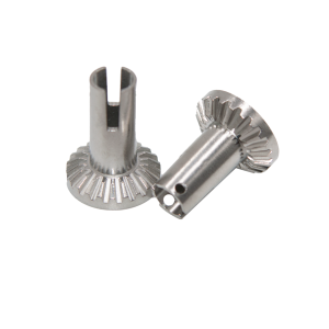
Spur gears, helical gears, bevel gears, worm gears, gear segments, splined shafts
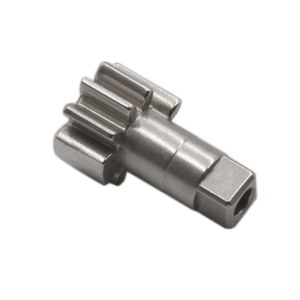
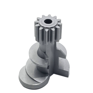
MIM is a natural fit for small to medium gears (module 0.3–1.5). The entire gear — teeth, bore, hub, face features — is molded in one shot. Case-hardening 8620 delivers tooth flank hardness matching wrought gear steel. For precision applications, post-sinter honing or gear rolling achieves AGMA Class 10.
Cam lobes, indexer cams, actuator drums, valve stems
Complex cam profiles that would require 4-axis CNC or EDM are standard in MIM. The as-molded surface finish (Ra 0.8–1.6µm) provides a smooth running surface directly from sintering. Hardened 440C or case-hardened 8620 delivers the surface durability required for cyclic cam-follower contact.
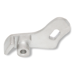
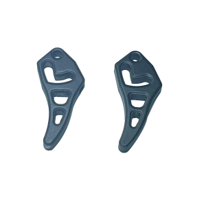
Toggle levers, bell cranks, connecting rods, shift forks, actuator arms
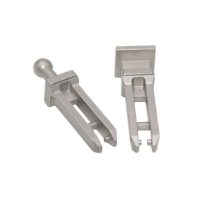
MIM excels at consolidating multi-part linkages into single components. A lever with an integrated bearing bore, a spring-retention hook, and a clevis pin hole — traditionally an assembly of 3–4 parts — becomes one MIM part. Weight-reducing pockets and reinforcing ribs are molded at no extra cost.
Locking pawls, ratchets, detent levers, latch components, hinge mechanisms
Directional tooth profiles, asymmetric detent ramps, and spring-loaded engagement surfaces are all moldable in MIM. The precision of molded ratchet teeth eliminates the post-machining and hand-fitting that cast or stamped pawls typically require.
Stepped shafts, splined spindles, camshafts, eccentric shafts
Small-diameter shafts with integrated features — splines, bearing journals, threaded ends, circlip grooves — are produced net-shape in MIM. Post-sinter grinding on bearing journals achieves the final diameter and roundness tolerance, while all other features emerge from the mold ready to use.
Gear housings, bearing housings, sensor enclosures, valve bodies
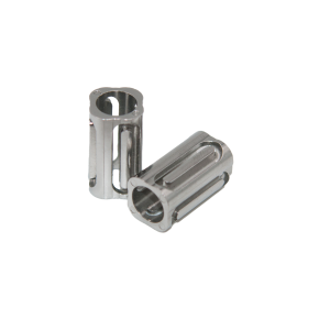
Thin-wall, complex-form housings with internal ribs, mounting bosses, and connector ports are ideal MIM candidates. The as-sintered density (≥95%) provides pressure-tight walls without impregnation — critical for fluid-handling housings.
A mechanical actuator required a gear sector with an integrated shaft and limit-stop pin. The original design: CNC gear sector + turned shaft + pressed-in pin = 3 parts, 3 suppliers, assembly labor. The MIM redesign consolidated all three into a single 8620 part — case-hardened teeth, integral shaft, molded stop feature. Result: 55% cost reduction, zero assembly fallout.
A robotic gripper linkage needed weight reduction to improve cycle speed. The original: machined 7075 aluminum with steel bushings press-fit into pivot bores. The MIM solution: 17-4PH steel linkage with I-beam cross-section and integral bearing bores — 30% lighter than the aluminum assembly through topology optimization, with higher strength and no galvanic corrosion risk.
A textile machine cam follower experienced premature wear on the hardened steel roller surface. The switch to MIM 440C (HRC 55–60) with a net-shape crowned profile on the roller OD eliminated the stress concentration at the roller edge — the failure initiation point. Wear life doubled, and per-part cost dropped 40% vs. the ground-and-lapped original.
1. Uniform wall thickness wherever possible.MIM, like plastic molding, benefits from uniform walls to control sintering shrinkage. Ribs and gussets should be 60–80% of the adjoining wall thickness.
2. Avoid sharp internal corners.A minimum 0.3mm radius on internal corners reduces stress concentration and improves mold filling. External corners can be sharp.
3. Design for the parting line.The mold parting line should ideally bisect the part along a plane of symmetry. Asymmetric parting lines increase tooling complexity and cost.
4. Plan for gate location.The gate — where molten feedstock enters the cavity — leaves a small vestige (0.2–0.5mm). Position it on a non-critical, non-cosmetic surface.
5. Leverage part consolidation.The biggest MIM cost savings come from eliminating assembly steps. Look for opportunities to combine multiple components — threaded bosses, retaining features, alignment pins — into one MIM part.
6. Consider post-sinter sizing for precision features.Bores, gear teeth, and engagement surfaces that require tight tolerances benefit from a post-sinter sizing or coining step. Design these features with 0.05–0.10mm of sizing stock.
Every production batch includes a sintered tensile bar processed alongside the parts. We test:
Certificates of conformance are provided with every shipment. Full material certifications (mill certs for feedstock powder, heat treat furnace charts) are available on request.
Q: At what production volume does MIM become more economical than CNC machining?
A: The crossover typically occurs at 5,000–10,000 annual pieces for simple parts, and 2,000–5,000 for complex parts with multiple machined features. The more complex the part geometry, the sooner MIM wins on cost.
Q: Can MIM parts be welded?
A: Yes. 17-4PH, 4140, and 316L MIM parts weld similarly to their wrought equivalents. The high density (≥95%) ensures minimal weld porosity. We recommend informing us during design review if welding is planned, so we can optimize the material and heat treatment sequence.
Q: How do you handle tight tolerances on gear bores?
A: Gear bores are typically sized post-sinter using a carbide sizing mandrel or honing. We hold H7 tolerance (±0.01–0.02mm) standard, with H6 (±0.006–0.01mm) available for high-precision applications. The gear teeth are roll-finished simultaneously to maintain concentricity.
Q: Is MIM suitable for parts that see impact loading?
A: Yes, with the right material selection. 8620 case-hardened parts combine a tough, low-carbon core with a hard case — ideal for impact-loaded gears and pawls. 4140 Q&T provides through-hardened toughness for structural impact components. We do not recommend high-hardness 440C (>HRC 55) for impact applications due to its lower toughness.
Q: What file formats do you accept for design submissions?
A: STEP (.stp/.step) and IGES (.igs) are preferred. We also accept native SolidWorks, Creo, and CATIA files. Include a 2D drawing with critical dimensions and tolerances for inspection reference.
Our MIM process is ISO 9001 certified with in-house heat treatment and full metallurgical testing capability. Visit Certifications and Design Guide for more information.
Have a mechanical component design ready for production? Send us your drawing or CAD model for a DFM analysis and quotation within 48 hours.

 Русский
 Español
 Deutsch
 日本語
日本語