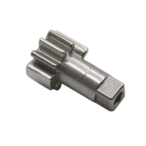
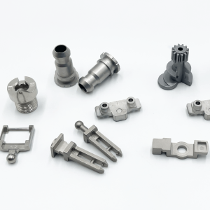
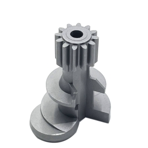
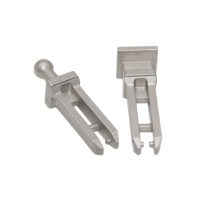
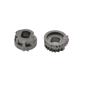
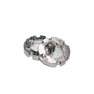
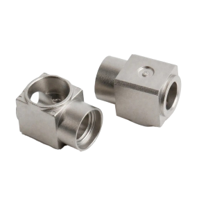
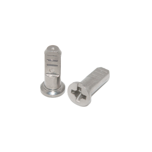
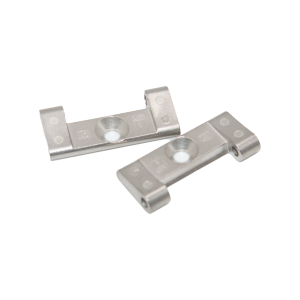
MIM Bearing Cage Retainer Manufacturer | Precision Linear Bearing ComponentsWhat Is a Bearing Cage Retainer?A bearing cage — also called a retainer or separator — is the component that holds rolling elements (balls, rollers, or needles) in position within a bearing assembly, maintaining equal spacing between them and preventing element-to-element contact. In linear motion systems — linear guides, ball splines, slide rails — the cage guides recirculating or oscillating bearing balls along a precise path, ensuring smooth, low-friction motion through millions of cycles. When manufactured throughMetal Injection Molding (MIM), bearing cages achieve complex pocket geometries — spherical ball pockets, curved recirculation channels, thin wall sections between pockets — in a single net-shape piece. The result is a precision retainer that matches the performance of machined or stamped cages at a significantly lower cost for complex geometries. This is a component where Japanese manufacturers have traditionally dominated.Precision-mim's MIM bearing cages offer equivalent precision at competitive pricing, with the added advantage of material flexibility — 440C for maximum hardness, 17-4PH for balanced strength and corrosion resistance, or 316L for harsh environments. |

|
| Property | 440C MIM (Hardened) | 17-4PH MIM (H900) | 316L Stainless MIM |
|---|---|---|---|
| Density | ≥ 7.5 g/cm³ | ≥ 7.6 g/cm³ | ≥ 7.7 g/cm³ |
| Hardness | HRC 55–60 | HRC 35–42 | HRB 65–75 |
| Ball Pocket Wear Resistance | ★★★★★ | ★★★★ | ★★ |
| Corrosion Resistance | ★★★★ | ★★★ | ★★★★★ |
| Dimensional Stability After Heat Treat | ★★★ | ★★★★★ | ★★★★★ |
| Non-Magnetic | No (magnetic) | Slightly magnetic | Yes |
| Best For | High-cycle linear guides, high-load retainers | General industrial, good corrosion + wear balance | Food-grade, medical, marine |
Selection guide:
A linear bearing cage typically contains 20–60 ball pockets, each an exact spherical or cylindrical cavity with specific clearance to the ball diameter. Machining these pockets one by one (EDM or CNC drilling + reaming) is slow and expensive. MIM molds all pockets simultaneously in a multi-cavity tool — all identical, all at net shape, all in a single molding cycle.
The wall between adjacent ball pockets can be as thin as 0.3mm in a MIM cage — critical for maximizing ball count in a given cage length. Stamping can produce thin walls but cannot achieve spherical pocket profiles. CNC machining can produce spherical profiles but struggles with thin walls. MIM does both.
In a linear guide, the clearance between ball and pocket affects running smoothness, noise, and ball recirculation reliability. MIM's mold-based replication ensures that every pocket in every cage has identical geometry. Post-sinter micro-bead blasting or tumbling uniformly deburrs pocket edges without changing critical dimensions.
Linear guide cages are not always flat — many are curved to follow a circular guide rail, or feature complex end profiles for recirculation turnarounds. 3D-contoured cages that would require 5-axis machining or costly EDM are routine in MIM, molded to net shape in one cycle.
| Feature | Capability |
|---|---|
| Ball diameter range | 1.0mm – 8.0mm |
| Pocket count per cage | 4 – 80+ |
| Minimum wall between pockets | 0.3mm |
| Pocket geometry | Spherical, cylindrical, tapered, elliptical |
| Cage profile | Flat, curved, circular, segmented |
| Pocket clearance tolerance | ±0.01mm (post-sizing) |
| Cage length | 5mm – 200mm |
| Cage width | 3mm – 50mm |
| Surface finish (as-sintered) | Ra 0.8–1.6µm |
| Surface finish (post-tumbled) |
Ra 0.4–0.8µm |
The core application. Linear guides used in CNC machines, 3D printers, semiconductor manufacturing equipment, and automation systems all rely on precision ball cages. MIM cages match the performance of ground-and-honed retainers at 40–60% lower cost for complex multi-pocket designs.
Ball splines transmit rotary torque while allowing axial movement. The retainer holds multiple rows of balls in precise axial and circumferential positions — a complex 3D geometry that MIM excels at producing.
The ball return path in a ball screw nut requires a precisely curved channel to guide balls from the loaded track back to the return tube. MIM molds these 3D-curved channels into a compact cap that bolts directly to the nut body.
Lightweight cages for thin-section bearings used in robotics, medical devices, and optical instruments. MIM's ability to produce thin walls (down to 0.3mm) and complex pocket shapes makes it ideal for these space-constrained applications.
Non-standard bearings — large-diameter slewing rings, segmented bearings, cam followers — often require custom cages in small to medium volumes. MIM's tooling cost is significantly lower than progressive stamping dies, making it economically viable for mid-volume custom retainers.
| Parameter | Capability |
|---|---|
| Part weight | 0.5g – 150g |
| Minimum wall thickness | 0.3mm |
| Ball pocket diameter tolerance | ±0.02mm (as-sintered) |
| Ball pocket position tolerance | ±0.03mm |
| Cage flatness | ≤ 0.05mm per 100mm |
| Heat treatment | Hardening (440C), H900 (17-4PH) |
| Surface finish options | As-sintered, micro-bead blasted, vibratory tumbled, passivated |
| Hardness testing | 100% lot sample Rockwell + microhardness traverse |
| Annual capacity | 20+ million pieces |
| Inspection |
Optical comparator pocket geometry + CMM critical dimensions |
Q: How does MIM 440C cage hardness compare to Japanese-manufactured cages?
A: MIM 440C achieves HRC 55–60 after vacuum hardening with deep cryogenic treatment — directly comparable to hardened 440C cages from Japanese manufacturers. The key difference is manufacturing method: our MIM process molds pockets to net shape vs. progressive stamping or EDM. Metallurgically, the material response to heat treatment is identical to wrought 440C at ≥95% theoretical density.
Q: Can you match the pocket geometry of an existing cage we currently source from Japan?
A: Yes. Send us a sample or drawing of your current cage. We reverse-engineer the pocket geometry — diameter, depth, spacing, edge radius — and replicate it in MIM. First-article samples are provided for your ball-fit and run-smoothness validation before production ramp.
Q: How do you ensure consistent ball-to-pocket clearance?
A: Pocket diameter is measured on an optical comparator for every cavity in a first-article cage, and sampled from multiple cavities on production parts. We typically hold ±0.02mm on pocket diameter. For high-precision guides requiring tighter control, post-sinter coining or sizing balls are run through the cage to burnish and size the pockets uniformly.
Q: What is the typical lead time for a new bearing cage project?
A: Tooling: 4–6 weeks. First-article samples (T0): 1–2 weeks after tool completion. After approval, production ramp: 2–3 weeks. Total: 8–10 weeks from PO. Rush tooling (3–4 weeks) is available for urgent projects at a premium.
Q: Can MIM cages be used in high-speed linear guides?
A: Yes, within standard linear guide speed ranges (up to 5 m/s for ball-type guides). For ultra-high-speed applications, we recommend a design review to optimize pocket edge geometry for smooth ball entry/exit during recirculation. MIM's net-shape edge radii produce less ball scuffing than sharp-edged stamped cages.
Q: How do MIM cages compare to polymer (PEEK/PAI) cages?
A: Metal cages (440C, 17-4PH) offer 5–10× the wear life of polymer cages in loaded linear guides, plus higher temperature capability and no moisture absorption. The trade-off is weight and noise — polymer cages are quieter. For high-load, high-precision, or high-temperature applications, MIM metal cages are the superior choice.
Our MIM process is ISO 9001 certified. Heat treatment is performed in-house with full batch traceability. CMM and optical comparator inspection reports accompany every shipment. Visit Certifications for details.
Currently sourcing bearing cages from Japan or Europe? Send us your current cage drawing or sample. We'll provide a DFM comparison and quotation within 48 hours — often at 30–50% cost reduction for equivalent precision.

 Русский
 Español
 Deutsch
 日本語
日本語