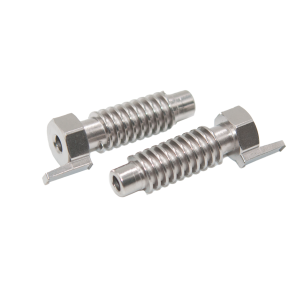
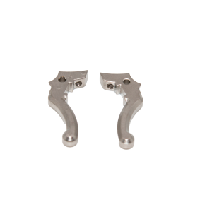
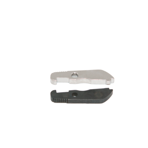
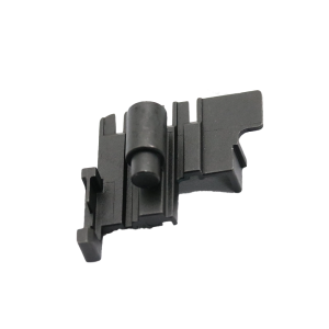
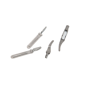
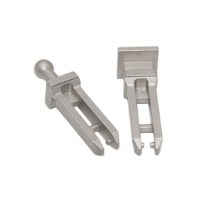
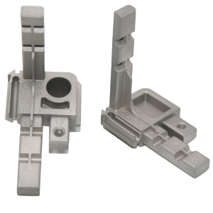
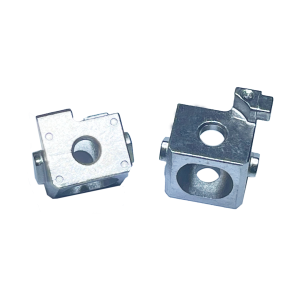
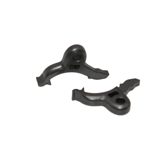
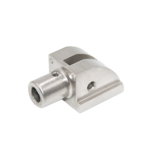
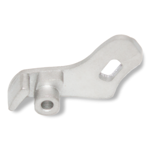
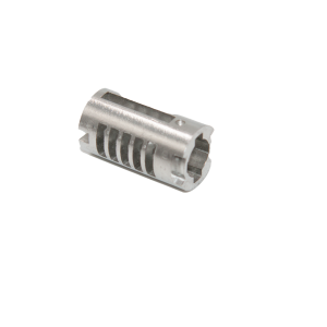
MIM Locating Pin Manufacturer | Precision Firearm Positioning ComponentsWhat Is a Locating Pin?A locating pin is a cylindrical or tapered positioning component that ensures precise alignment between two mating parts in a mechanical assembly. In firearm and air gun systems, locating pins serve as fixed reference points — they lock components like the barrel, receiver, trigger housing, and bolt assembly into exact spatial relationships, ensuring repeatable accuracy shot after shot. When manufactured throughMetal Injection Molding (MIM), locating pins achieve complex features — stepped diameters, tapered ends, undercuts for snap-fit retention, and anti-rotation flats — in a single net-shape process. No secondary turning, no multi-step machining. The result is a high-strength, high-consistency positioning component at a fraction of the cost of CNC-machined equivalents. |

|
We offer three standard material grades, each suited to different performance requirements:
| Property | 17-4PH MIM | 4140 Steel MIM | 316L Stainless MIM |
|---|---|---|---|
| Density | ≥ 7.6 g/cm³ | ≥ 7.5 g/cm³ | ≥ 7.7 g/cm³ |
| Tensile Strength | ≥ 950 MPa (heat-treated) | ≥ 1,000 MPa (heat-treated) | ≥ 480 MPa |
| Yield Strength | ≥ 850 MPa (H900) | ≥ 800 MPa (Q&T) | ≥ 170 MPa |
| Hardness | HRC 35–42 (H900) | HRC 38–45 (Q&T) | HRB 65–75 |
| Elongation | 6–10% | 8–12% | 40–50% |
| Corrosion Resistance | ★★★ | ★★ (requires coating) | ★★★★★ |
| Best For | High-strength, moderate corrosion resistance | Maximum strength, cost-sensitive | Harsh environments, full corrosion immunity |
Selection guide:
A locating pin with a stepped shaft, a tapered lead-in, and an anti-rotation flat traditionally requires at least 3 separate machining operations. With MIM, all these features are molded in the green part and preserved through sintering — saving 60–80% on machining cost and eliminating tool-change tolerance drift.
In firearm assembly, a locating pin that's 0.02mm too tight or too loose compromises the entire action. MIM's tool-based replication ensures that every pin from a production run fits identically — critical for OEMs producing thousands of units per month.
As-sintered Ra 0.8–1.6µm means locating pins slide smoothly into mating bores without galling or binding. Optional micro-polishing or passivation further reduces insertion force for automated assembly lines.
Unlike screw-machine production — which is typically limited to free-machining grades — MIM supports high-performance alloys that are difficult or impossible to turn on a lathe, including precipitation-hardened 17-4PH and high-carbon 4140.
| Feature | Capability |
|---|---|
| Diameter range | 1.5mm – 15mm |
| Length range | 3mm – 60mm |
| Tip styles | Flat, chamfered, bullet-nose, tapered (1°–15°) |
| Shaft features | Stepped diameters, undercut groove, cross-hole, knurled section |
| Head styles | Flanged, countersunk, hex socket, slotted |
| Anti-rotation | D-flat, double-flat, hex body |
| Tolerances (as-sintered) | ±0.3% (typically ±0.025mm on diameter) |
| Tolerances (with sizing) |
±0.01mm |
Locating pins position the barrel relative to the receiver, setting headspace and bore alignment. MIM's dimensional repeatability ensures consistent lock-up across every unit in production.
In modular trigger assemblies (AR-style drop-in units, pistol fire control groups), locating pins fix the housing in the receiver with zero play. Post-sinter sizing achieves the exact interference or slip fit your design specifies.
Guide pins in bolt-action and semi-automatic actions experience cyclic shear loading. 4140 heat-treated MIM pins absorb these loads without deformation, maintaining bolt travel consistency over tens of thousands of cycles.
Small-diameter locating pins (1.5–3mm) in magazine release mechanisms require high surface hardness to resist wear from repeated magazine changes. 17-4PH H900 delivers HRC 35–42 without the brittleness of fully hardened tool steel.
In pre-charged pneumatic (PCP) and spring-piston air guns, locating pins align the compression chamber, trigger sear, and barrel pivot. MIM enables complex geometries — such as a pin with an integrated spring-retention groove — in a single piece.
| Parameter | Capability |
|---|---|
| Part weight | 0.05g – 50g |
| Minimum diameter | 1.5mm |
| Minimum wall (groove depth) | 0.3mm |
| As-sintered tolerance | ±0.3% of nominal dimension |
| Sizing tolerance | ±0.01mm |
| Annual capacity | 100+ million pieces |
| Heat treatment | H900 (17-4PH), quench & temper (4140) |
| Surface finish options | As-sintered, micro-polished, passivated, black oxide |
| Inspection | 100% go/no-go gauge on critical diameters; CMM sampling per AQL |
Q: Can a MIM locating pin hold the same tolerance as a ground dowel pin?
A: As-sintered MIM achieves ±0.3% (≈±0.02mm on a 6mm pin). For tighter requirements, post-sinter sizing operations bring critical diameters to ±0.01mm — equivalent to a ground pin but at a significantly lower cost for complex geometries.
Q: What is the minimum order quantity?
A: We typically quote for 5,000 pieces and above, with the strongest cost advantage at 20,000+ annual volumes. For prototyping, we can produce sample quantities (50–200 pieces) from the production tool to validate fit and function before volume ramp-up.
Q: Do MIM locating pins require a surface coating?
A: 17-4PH and 316L offer inherent corrosion resistance that often eliminates the need for coating. 4140 steel locating pins benefit from black oxide or phosphating for corrosion protection — both available in-house. We'll recommend the best approach based on your operating environment.
Q: How do you ensure consistent interference fit across a production run?
A: For press-fit applications, we apply a post-sinter sizing operation on the engagement diameter. Statistical process control (SPC) tracking tracks Cp/Cpk across every batch. We report critical-dimension capability data with each shipment.
Q: Can you produce locating pins from my existing CAD model?
A: Yes. We accept STEP, IGES, and native SolidWorks/Creo files. Our engineering team will review your design for MIM manufacturability — including gate placement, parting line location, and shrink factor compensation — and return a DFM (Design for Manufacturing) report before tooling begins.
Our MIM process is certified to ISO 9001. Visit our Quality Assurance page for full certification details.
Ready to discuss your locating pin requirements? Send us your specifications or a drawing and we'll provide a manufacturability assessment within 48 hours.

 Русский
 Español
 Deutsch
 日本語
日本語