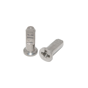
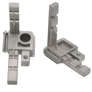
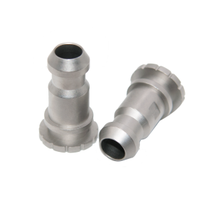
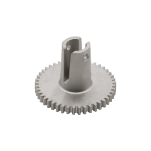
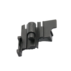
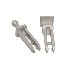
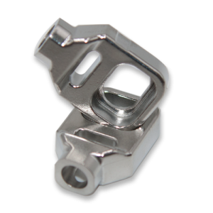
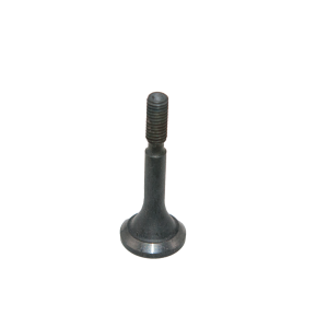
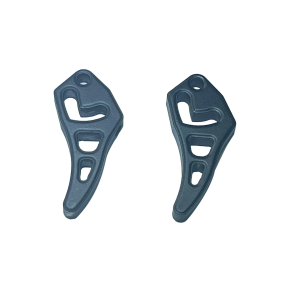
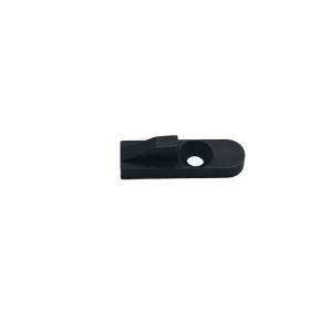
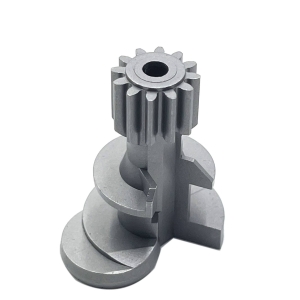
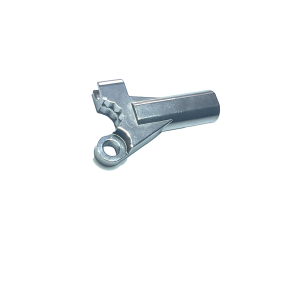
MIM Communications Connector | Precision Signal Components for Telecom EquipmentWhat Is a Communications Connector?A communications connector is a precision-engineered signal component that enables reliable transmission of electrical or RF (radio frequency) signals between circuit boards, modules, and external interfaces within communication equipment. In modern telecom systems — from 5G base stations to fiber-optic network terminals — the connector is not just a mechanical interface; it is anactive participant in signal integrity. Every impedance mismatch, every surface imperfection, every microscopic gap in a connector body introduces signal reflection, attenuation, or crosstalk — degrading the very data the system is designed to carry. At gigahertz frequencies, these effects multiply. Metal Injection Molding (MIM)addresses this challenge uniquely: it produces connector bodies, housings, and contact carriers with the geometric precision and surface quality that high-frequency applications demand, in materials that maintain dimensional stability across the telecom equipment's operating temperature range (typically -40°C to +85°C). At Precision-mim, we manufacture communications connectors in austenitic stainless steels (304, 316L) and specialty alloys — delivering the repeatability and signal consistency that network equipment manufacturers require. |

|
In high-frequency communication systems, the connector body is part of the transmission line. Its geometry directly affects three critical signal parameters:
Characteristic Impedance: Determined by the ratio of inner conductor diameter to outer conductor (body) diameter and the dielectric constant of the insulating material between them. Dimensional variation in the connector body directly shifts impedance away from the target (typically 50Ω or 75Ω), causing reflection losses.
Insertion Loss: Surface roughness inside the connector body scatters RF energy, increasing signal attenuation. MIM's as-sintered surface finish (Ra 0.8–1.6 µm) is comparable to fine machining and can be electropolished to Ra <0.4 µm for millimeter-wave applications.
Passive Intermodulation (PIM): In multi-carrier systems, non-linearities at metal-to-metal contact points generate intermodulation products that appear as noise in the receive band. MIM's ability to form seamless, monolithic connector bodies eliminates ferromagnetic contamination and reduces contact interfaces — two primary sources of PIM.
| Material | Best For | Key Properties |
|---|---|---|
| 316L Stainless Steel | Outdoor base stations, coastal installations, high-humidity environments | Maximum corrosion resistance, non-magnetic, 510+ MPa tensile |
| 304 Stainless Steel | Indoor networking equipment, enterprise routers, data center interconnects | Good corrosion resistance, cost-effective, 480+ MPa tensile |
| Fe-50Ni (Kovar equivalent) | Glass-to-metal sealed connectors, hermetic feedthroughs | Thermal expansion matched to borosilicate glass, controlled CTE |
| Copper alloys (MIM) | High-current power connectors, grounding interfaces | Superior electrical conductivity, effective thermal management |
For most general communications connectors,304 or 316Lprovides the ideal balance of mechanical strength, environmental resistance, and cost. The non-magnetic property of both austenitic grades (magnetic permeability <1.02) eliminates signal distortion from ferromagnetic interference — a critical consideration for RF connectors.
A typical communications connector body may require: a precision bore for the center contact insulator, external threads for coupling nuts, internal snap-ring grooves for retention, anti-rotation flats, panel-mount flanges with mounting holes, and cable-entry strain-relief features. Machining this from bar stock requires 6–8 separate operations, multiple fixtures, and still leaves tool-mark stress concentrations at internal corners.
MIM molds all of these features simultaneouslyin a single green part. The sintered component needs only thread chasing and electropolishing — no multi-setup machining, no brazed-on flanges, no press-fit inserts.
RF connector performance is only as good as its worst unit. Dimensional lot-to-lot variation from multi-setup machining creates impedance outliers that fail network testing. MIM's single-cavity-to-multi-cavity tooling approach ensures every connector body in a production run shares identical geometry — your RF test data will show tighter distributions on VSWR (Voltage Standing Wave Ratio) and insertion loss.
At frequencies above 3 GHz, the skin effect concentrates current flow in the outermost few microns of the conductor surface. Surface roughness in this layer directly increases effective resistance and insertion loss. MIM's as-sintered finish (Ra 0.8–1.6 µm) is on par with fine machining. For critical applications (5G millimeter-wave, satellite communications), electropolishing achieves Ra <0.4 µm — an order of magnitude smoother than as-cast or die-cast alternatives.
Communication equipment deployed outdoors — base stations, antenna interfaces, microwave backhaul links — faces rain, humidity, salt fog, and temperature swings. Plated connector bodies (zinc die-cast + nickel/chrome, machined brass + nickel/gold) eventually develop pinhole defects in the plating layer, leading to galvanic corrosion at the substrate interface.
MIM 316L connectors eliminate this failure mode entirely: the corrosion resistance is the material itself, not a coating. For coastal 5G installations where salt spray is a daily reality, this is not a luxury — it's a reliability requirement.
A multi-piece machined connector assembly (body + flange + coupling ring + retainer) often becomes a single MIM part. Each eliminated interface removes a potential PIM source, reduces assembly labor, and simplifies supply
RRU (Remote Radio Unit) connectors, antenna array interfaces, and filter housing connectors. The high density of 5G antenna elements (64T64R or 128T128R massive MIMO arrays) creates an unprecedented demand for compact, high-performance RF connectors — precisely where MIM's ability to miniaturize complex geometries delivers the most value.
ONT (Optical Network Terminal) housings, SFP/SFP+ cage components, and fiber connector alignment sleeves. While the optical path is glass, the mechanical alignment components must maintain micron-level precision through thermal cycling — MIM stainless steel's dimensional stability makes it the material of choice.
High-density backplane connectors, server rack interfaces, and power distribution connectors. Data centers operate 24/7 in temperature-controlled environments, but connector density (hundreds per rack) makes unit cost and reliability paramount. MIM delivers both at scale.
LNB (Low Noise Block) feedhorn bodies, waveguide transitions, and antenna mounting interfaces. These components operate in extreme environments — vacuum, radiation, thermal extremes — where outgassing from plated or coated parts is unacceptable. Solid MIM stainless steel eliminates this concern.
Ruggedized Ethernet connectors (M12, RJ45 industrial), sensor interface connectors, and fieldbus connectors for factory automation. MIM's combination of environmental sealing geometry (molded O-ring grooves) and corrosion resistance makes it ideal for IP67/IP68-rated industrial connectors.
Precision calibration connectors, VNA (Vector Network Analyzer) test port interfaces, and RF switch matrices. The metrology-grade repeatability requirements of test equipment make MIM's dimensional consistency particularly valuable.
| Criterion | MIM 316L | Machined Brass + Plated | Die-Cast Zinc + Plated | Machined Stainless |
|---|---|---|---|---|
| Complex internal geometry | ★★★★★ | ★★★ | ★★★★ | ★★★ |
| RF surface quality | ★★★★ (★★★★★ electropolished) | ★★★★★ | ★★ | ★★★★★ |
| PIM performance | ★★★★★ (fewer interfaces) | ★★★★ | ★★ | ★★★★ |
| Corrosion resistance | ★★★★★ (bulk) | ★★ (plating-dependent) | ★ (plating-dependent) | ★★★★★ |
| Non-magnetic | ✅ | ✅ | ❌ (paramagnetic) | ✅ |
| Unit cost @ 10k+ volume | ★★★★★ | ★★ | ★★★ | ★ |
| Dimensional consistency (batch) | ★★★★★ | ★★★ | ★★★ | ★★★ |
| Environmental durability | ★★★★★ | ★★ | ★ | ★★★★★ |
| Parameter | Capability |
|---|---|
| Material | 304, 316L stainless steel; Fe-50Ni; copper alloys |
| Part weight range | 0.3g – 100g |
| Minimum wall thickness | 0.3 mm |
| Dimensional tolerance (as-sintered) | ±0.3% of nominal |
| Internal bore tolerance | ±0.02 mm (with secondary honing) |
| Thread features | Molded external threads; tapped or threaded-insert internal threads |
| Surface finish (as-sintered) | Ra 0.8 – 1.6 µm |
| Surface finish (electropolished) | Ra <0.4 µm |
| Magnetic permeability (304/316L) | <1.02 |
| Impedance-critical features | ±0.05 mm achievable with coining |
| Annual production capacity | 50+ million pieces |
Q: Can MIM achieve the dimensional precision required for RF connectors operating above 6 GHz?
A: Yes. For impedance-critical dimensions (inner bore diameter, dielectric cavity depth), as-sintered MIM achieves ±0.3% of nominal — typically ±0.05 mm on connector-scale features. For millimeter-wave applications (24 GHz+), secondary coining or honing tightens this to ±0.02 mm. Our process capability studies for RF connector bodies show CpK >1.33 on all critical-to-function dimensions.
Q: How do MIM stainless steel connectors perform on PIM (Passive Intermodulation) testing?
A: PIM performance in MIM connectors benefits from two inherent advantages: (1) fully dense, non-magnetic microstructure with no ferromagnetic contamination (unlike machined brass which can pick up ferrous particles from tooling), and (2) monolithic body construction that eliminates metal-to-metal interfaces where PIM originates. Typical PIM levels for properly designed MIM 316L connector bodies are better than -165 dBc @ 2×43 dBm — meeting carrier-grade specifications for 4G/5G infrastructure.
Q: Are MIM connectors suitable for hermetic (glass-to-metal sealed) feedthrough applications?
A: Yes, when produced in Fe-50Ni alloy (Kovar equivalent). The controlled thermal expansion coefficient of Fe-50Ni MIM material matches borosilicate glass sealing temperatures, enabling reliable hermetic seals for pressurized waveguide and vacuum feedthrough applications. We validate hermeticity to <1×10⁻⁹ Pa·m³/s helium leak rate.
Q: Can you produce connector bodies with integrated EMI shielding features?
A: Yes. MIM can form shielding walls, grounding tabs, and spring-finger EMI gaskets directly into the connector body — features that would require separate beryllium-copper stampings or conductive elastomer gaskets in a traditional design. The monolithic construction also eliminates slot-antenna effects caused by gaps between assembled shielding components.
Q: What's the lead time for a custom communications connector design?
A: Tooling lead time is 3–4 weeks from finalized CAD to first-article samples. Full production ramp typically takes 6–8 weeks from sample approval, including process qualification and first-article inspection reports (FAIR) per AS9102 or customer-specific formats.
Learn more about our MIM process capabilities and material options for communication-grade components.
Have a connector design or RF performance specification? Send us your drawing for a DFM review and feasibility assessment.

 Русский
 Español
 Deutsch
 日本語
日本語