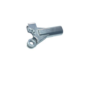
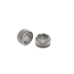
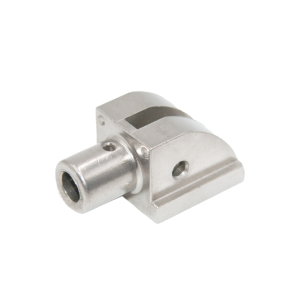
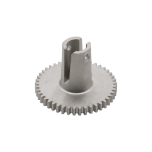
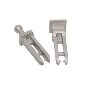
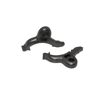
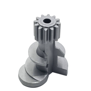
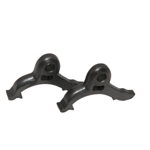
MIM Stainless Steel Quick-Connect Locking Connectors — Precision Coupling Components
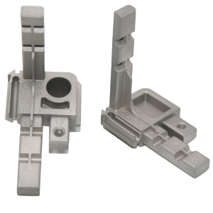
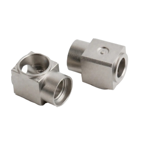
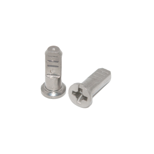
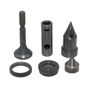
What Is a Locking Connector?A locking connector is a precision mechanical component that secures electrical or signal connections through a positive-lock mechanism — preventing accidental disconnection from vibration, thermal cycling, or mechanical stress. When manufactured throughMetal Injection Molding (MIM), these connectors achieve complex internal geometries, tight tolerances, and consistent mechanical properties at production volumes that would be uneconomical through CNC machining. Locking connectors are critical in applications where a failed connection means system downtime, signal degradation, or safety hazards — think telecommunications base stations, industrial control cabinets, power distribution units, and outdoor communication equipment exposed to wind, rain, and temperature extremes. At Precision-mim, we specialize in MIM stainless steel 304 locking connectors that combine the material's natural corrosion resistance with the design freedom of injection molding. The result: a single-piece connector body with integrated locking tabs, spring features, threaded elements, and mounting provisions — no assembly, no welding, no compromise.
|

|
Locking connectors are deceptively complex. A typical design requires:
CNC machining such a part from bar stock would require multiple setups, custom fixturing, and still leave material waste exceeding 70%. Stamping is limited to flat geometries. Die casting lacks dimensional precision and surface quality.
MIM solves all of these simultaneously.The connector body is injection-molded as a single green part, then sintered to near-full density — producing a finished component that requires zero secondary machining for functional features.
| Property | Value (MIM SS304) | Relevance to Connectors |
|---|---|---|
| Density | ≥ 7.6 g/cm³ | Mass-efficient for panel-mounted connectors |
| Tensile Strength | 480 – 520 MPa | Withstands insertion/removal forces over thousands of cycles |
| Yield Strength | 170 – 200 MPa | Spring tabs maintain locking force without permanent deformation |
| Elongation | 40 – 50% | Ductility absorbs mechanical shock without fracture |
| Hardness | HRB 65 – 75 | Resists wear from repeated mating cycles |
| Corrosion Resistance | Passes 48h salt spray (ASTM B117) | Reliable in outdoor/humid environments |
| Magnetic Permeability | < 1.02 (non-magnetic) | No signal interference in RF applications |
| Surface Finish (as-sintered) | Ra 0.8 – 1.6 µm | Smooth mating surfaces without secondary polishing |
The locking tab, spring arm, or bayonet feature is molded directly into the connector body — not added as a separate component. This eliminates tolerance stack-up between the lock and body, reduces assembly steps, and removes potential failure points. The locking force is consistent from the first cycle to the 10,000th.
Internal cable channels, wire guides, seal grooves, and snap-fit retention rings are all formed during injection molding. There are no tool-access constraints, no minimum-radius limitations of end mills, and no setups to flip. If you can design it in CAD, MIM can likely mold it.
SS304's inherent corrosion resistance eliminates the need for electroplating or coating — a critical advantage for connectors. Plating on machined connectors inevitably wears off at high-contact-cycle points, exposing the base metal to oxidation and creating intermittent contact failures. MIM SS304 connectors maintain their corrosion protection throughout their service life because it's the material itself, not a surface treatment.
Spring-force consistency in stamped or machined connectors depends on precise control of cold-working, grain orientation, and heat treatment — variables that introduce batch-to-batch variation. MIM's sintering process achieves uniform microstructure throughout every part in a batch, producing locking-tab spring forces with ±5% repeatability.
When annual volumes exceed 10,000 pieces, MIM locking connectors cost 40–60% less than equivalent CNC-machined parts. The savings come from: near-net-shape forming (minimal material waste), single-step production (no multi-setup machining), and elimination of assembly steps (integrated features).
Base station connectors, antenna feed-throughs, and weatherproof equipment enclosure connectors. Outdoor telecom installations demand connectors that maintain locking integrity through thermal cycling (-40°C to +85°C) and resist salt-spray corrosion for decades — exactly the envelope where MIM SS304 excels.
PLC I/O module connectors, sensor cable interfaces, and fieldbus connectors in factory automation. These connectors are subjected to vibration, oil mist, and frequent connect/disconnect cycles. The integrated locking mechanism prevents signal loss from accidental unmating.
Panel-mounted power connectors, busbar terminals, and disconnect switches. High current-carrying capacity combined with positive locking ensures safe, reliable power delivery in electrical cabinets and switchgear.
ECU connectors, sensor connectors, and wiring-harness interfaces. Under-hood environments combine heat, vibration, and chemical exposure — conditions that rapidly degrade plastic-bodied connectors but are handled routinely by SS304 MIM parts.
Waterproof connector bodies for outdoor LED fixtures, street lighting, and architectural illumination. The non-magnetic property of sintered SS304 is essential for luminaires using magnetic mounting systems.
Patient monitor connectors, diagnostic equipment interfaces, and surgical tool cable connections. SS304's biocompatibility and autoclave tolerance make MIM connectors suitable for medical environments where sterilization is routine.
| Criterion | MIM SS304 | CNC Machined Brass + Plated | Die-Cast Zinc + Plated | Stamped Steel + Plated |
|---|---|---|---|---|
| Complex internal geometry | ★★★★★ | ★★★ | ★★★★ | ★ |
| Corrosion resistance | ★★★★★ (bulk material) | ★★★ (coating-dependent) | ★★ (coating-dependent) | ★★ (coating-dependent) |
| Locking-mechanism integration | ★★★★★ | ★★★ | ★★★★ | ★★ |
| Spring-force repeatability | ★★★★★ | ★★★ | ★★ | ★★★ |
| Unit cost @ 10k+ volume | ★★★★★ (lowest) | ★★ (high) | ★★★ (medium) | ★★★★ (low) |
| Surface quality (as-produced) | ★★★★ | ★★★★★ | ★★★ | ★★★ |
| Environmental durability (no coating) | ★★★★★ | ★ (bare brass tarnishes) | ★ (zinc corrodes) |
★ (steel rusts) |
| Parameter | Capability |
|---|---|
| Material | SS304 (AISI 304 / EN 1.4301) |
| Part weight range | 0.5g – 80g |
| Minimum wall thickness | 0.3 mm |
| Dimensional tolerance (as-sintered) | ±0.3% of nominal |
| Thread features | Molded external threads; tapped internal threads available |
| Mating cycle rating (typical) | 5,000 – 50,000 cycles (design-dependent) |
| Surface treatments | Passivation, electropolishing, PVD coating |
| Annual capacity | 50+ million pieces |
| Prototyping lead time | 3–4 weeks (tooling + first samples) |
Q: Can you mold internal snap-fit retention features that don't require threads?
A: Yes. Snap-fit geometries — cantilever snaps, annular snaps, and torsional retention rings — are well-suited to MIM because the tooling can form undercuts through side-actions or collapsible cores. This is one of MIM's signature advantages over machining.
Q: How do you ensure locking-tab spring force stays consistent?
A: Spring consistency is controlled through powder particle size distribution (uniform packing density), mold temperature uniformity (even filling), and sintering profile optimization (uniform grain growth). We validate lock force on every production batch using a calibrated force gauge with statistical process control limits.
Q: Can SS304 MIM connectors handle outdoor exposure without additional coating?
A: Yes. SS304's chromium oxide passive layer provides effective corrosion protection in most outdoor environments. For coastal or heavy-industrial exposure, we recommend passivation treatment which enhances the passive layer. For the most aggressive environments (offshore, chemical plants), we can produce the same connector in 316L.
Q: What about electrical conductivity — is MIM SS304 conductive enough for current-carrying connectors?
A: SS304 has lower conductivity than copper or brass (~2.4% IACS). For pure signal connectors, this is irrelevant. For power connectors carrying significant current, we recommend designing the contact interface as a separate copper-alloy insert that the MIM body houses and retains — combining SS304's structural benefits with copper's conductivity where it matters.
Q: What file formats do you accept for connector designs?
A: STEP (.stp), IGES (.igs), and native SolidWorks (.sldprt) files are standard. We also accept 2D drawings with GD&T callouts for critical-to-function features.
For more about the MIM process and material options, visit our Manufacturing Process and Material Guide pages.
Have a connector design? Send your drawing or 3D model for a same-day DFM review.

 Русский
 Español
 Deutsch
 日本語
日本語