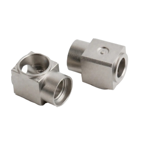
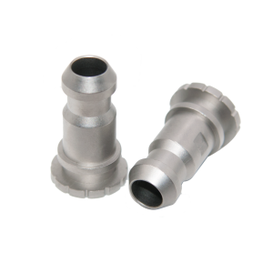
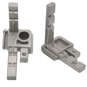
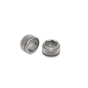
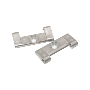
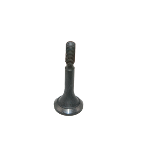
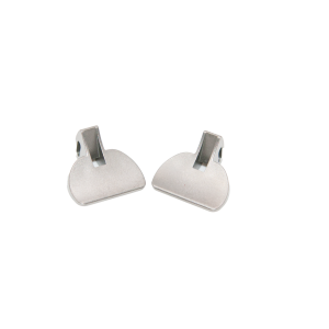
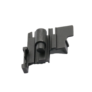
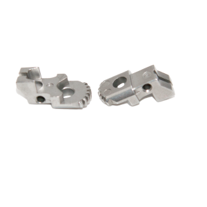
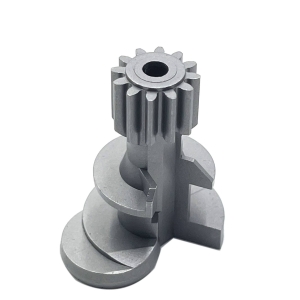
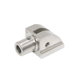
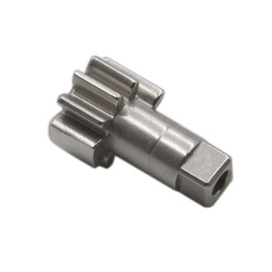
MIM Stainless Steel Locking and Inserting Parts | Precision Electrical Connector ComponentsWhat Are Locking and Inserting Parts?Locking and inserting parts are the core mechanical interface in an electrical connector system: the male insert body that carries contacts or pins, and the female receptacle with its integrated locking mechanism that secures the connection. Together, they form the plug-and-socket pair that enablesreliable, repeatable electrical matingacross thousands of connection cycles. These are not simple turned pins or stamped sockets. A modern MIM locking-and-inserting component typically integrates multiple functional features into a single monolithic part:
At Precision-mim, we manufacture these components in stainless steel 304 through the MIM process — achieving the complex internal geometry, consistent dimensional accuracy, and cost efficiency that high-volume electrical connector production demands. |

|
While the outer connector body (housing) provides environmental protection and mechanical mounting, the locking and inserting parts are thefunctional coreof the connection. They determine:
This is why locking and inserting parts are the highest-precision components in any connector assembly. They are the difference between a connector that works reliably for 15 years in a telecom base station and one that generates service calls after 18 months.
| Property | Value (MIM SS304) | Why It Matters |
|---|---|---|
| Density | ≥ 7.6 g/cm³ (>96% theoretical) | Near-wrought strength for contact retention |
| Tensile Strength | 480 – 520 MPa | Resists insertion/withdrawal mechanical stress |
| Yield Strength | 170 – 200 MPa | Locking ramps maintain spring-back without permanent set |
| Elongation | 40 – 50% | Ductility prevents brittle fracture under side-load or drop impact |
| Hardness | HRB 65 – 75 | Contact cavity walls resist wear from pin insertion |
| Magnetic Permeability | < 1.02 (non-magnetic) | No interference with signal transmission |
| Corrosion Resistance | Passes 48h salt spray (ASTM B117) | Reliable in outdoor and industrial environments |
| Surface Finish (as-sintered) | Ra 0.8 – 1.6 µm | Smooth contact cavity walls reduce insertion friction |
A typical locking insert body contains 4 to 20+ contact cavities, each requiring sub-0.05 mm positional accuracy relative to the mating face. Between those cavities: thin walls (often 0.3–0.5 mm) that provide electrical isolation, locking detents with precise ramp angles, and internal retention features (snap-ring grooves, shoulder stops, barbed retention fingers).
Manufacturing this from bar stock through CNC machining means:
MIM solves this in one shot. The entire part — cavities, walls, locking features, retention geometry — is formed simultaneously during injection molding. The sintered part requires only thread chasing and surface treatment, reducing per-part manufacturing time from minutes to seconds.
Contact position accuracy is critical to connector performance. MIM's tooling-based replication ensures every cavity in every part is positioned within ±0.3% of nominal — and often within ±0.05 mm on connector-scale features. This consistency translates directly to reliable pin-socket alignment and consistent insertion force across the entire production run.
Instead of assembling separate spring clips, locking rings, or detent balls into a machined body, MIM forms the locking ramp, detent notch, or bayonet track directly into the insert body. The monolithic construction eliminates tolerance stack-up between the lock and the body — the single most common source of inconsistent mating feel in assembled connectors.
The walls between adjacent contact cavities must be thin to keep the connector compact while maintaining sufficient dielectric separation. MIM routinely achieves 0.3 mm wall thickness in SS304 — impossible to machine without wall collapse from cutting forces — while maintaining full density and mechanical integrity through sintering.
Polarization features (asymmetric pin patterns, keying ribs, D-shaped profiles) that prevent incorrect insertion are molded directly into the part. No broaching, no milling of keyways, no press-fit polarizing pins. The feature is as precise and repeatable as the mold that creates it.
For annual quantities above 10,000 pieces, MIM locking and inserting parts cost 40–60% less than multi-setup CNC machining. The savings multiply when you factor in eliminated assembly steps (integrated locking, strain relief, mounting features), reduced QC inspection (fewer dimensions to verify when fewer operations are involved), and lower scrap rates (near-net-shape with minimal material waste).
RJ45 modular plug bodies, fiber-optic connector inserts (LC, SC, MPO), and backplane connector contact carriers. The telecom industry's move to higher port densities (48+ ports per 1RU panel) demands inserts with ever-thinner walls and tighter cavity spacing — precisely where MIM excels.
M12 and M8 circular connector inserts, heavy-duty rectangular connector contact carriers (Harting/Weidmüller type), and fieldbus connector bodies. Industrial environments subject connectors to vibration, oil mist, and temperature cycling — conditions where plated die-cast inserts eventually fail but solid SS304 MIM parts endure.
ECU connector inserts, sensor connector contact carriers, and high-voltage EV connector bodies. Under-hood thermal cycling and vibration exposure make insert body integrity critical to avoiding intermittent electrical faults that trigger check-engine lights.
High-current connector inserts for busbar systems, panel-board connector bodies, and industrial power plug inserts. The combination of electrical insulation requirements (thin walls between phases) and mechanical robustness (withstanding insertion forces on large-gauge contacts) makes MIM the ideal process.
MIL-DTL-38999 type connector inserts, circular connector contact retention discs, and avionics rack connector bodies. The demanding environmental and reliability requirements (salt fog, thermal shock, vibration, altitude) are met by SS304 MIM's full-density, non-magnetic, corrosion-proof properties — without the cost and lead time of aerospace-grade machining.
Patient monitor connector inserts, surgical instrument cable interfaces, and diagnostic equipment contact carriers. Biocompatibility and autoclave tolerance make MIM SS304 suitable for medical environments where connectors must survive repeated sterilization cycles without degradation.
| Criterion | MIM SS304 | CNC Machined Brass | Die-Cast Zinc | Injection-Molded LCP/PEI |
|---|---|---|---|---|
| Multi-cavity precision | ★★★★★ | ★★★ | ★★ | ★★★★ |
| Wall thickness (minimum) | 0.3 mm | ~0.5 mm (deformation risk) | ~0.8 mm | 0.2 mm |
| Locking feature integration | ★★★★★ | ★★ | ★★★★ | ★★★ |
| Mechanical strength | ★★★★ | ★★★ | ★★ | ★ |
| Contact retention life | ★★★★★ | ★★★ | ★★ | ★ (creep) |
| Temperature resistance | ★★★★ (300°C) | ★★★ (200°C) | ★ (softens ~100°C) | ★★★ (260°C LCP) |
| Corrosion resistance | ★★★★★ (bulk) | ★★ (plating needed) | ★ (plating needed) | ★★★★★ (inherent) |
| Unit cost @ 10k+ volume | ★★★★★ | ★★ | ★★★ | ★★★★ |
| EMI shielding | ★★★★★ (conductive) | ★★★★★ | ★★★★★ | ★ (requires coating) |
Key trade-off: Plastics (LCP/PEI) can achieve thinner walls and lower unit costs but lack the mechanical robustness and EMI shielding of metal. Zinc die-cast is cheap but fails on strength, precision, and environmental durability. Machined brass is precise but expensive and requires plating. MIM SS304 hits the sweet spot: metal performance with molding economics.
| Parameter | Capability |
|---|---|
| Material | SS304 (AISI 304 / EN 1.4301) |
| Part weight range | 0.2g – 60g |
| Minimum wall thickness | 0.3 mm |
| Contact cavity positional tolerance | ±0.05 mm (typical) |
| Dimensional tolerance (as-sintered) | ±0.3% of nominal |
| Cavity ID tolerance | ±0.02 mm (with secondary honing) |
| Thread features | Molded external threads; tapped internal threads |
| Locking detent angle tolerance | ±0.5° |
| Surface finish (as-sintered) | Ra 0.8 – 1.6 µm |
| Surface treatments | Passivation, electropolishing |
| Mating cycle rating (typical) | 5,000 – 50,000 cycles (design-dependent) |
| Annual production capacity | 50+ million pieces |
Q: How do you maintain contact cavity position accuracy across high-volume production?
A: Cavity position accuracy is built into the mold — every part from the same tooling shares identical cavity locations. We validate positional accuracy on first-article inspection using CMM (Coordinate Measuring Machine) and maintain it through production with statistical process control on critical dimensions. Multi-cavity tools undergo cavity-to-cavity qualification to ensure all cavities produce within-tolerance parts.
Q: Can you mold retention features for clip-in contacts — not just cylindrical bores?
A: Yes. Barbed retention fingers, snap-fit ledges, shoulder stops, and cantilever retention clips can all be molded directly into the insert body cavity. These are formed by side-actions or collapsible cores in the injection mold — geometries that would require EDM or broaching if machined, but are routine in MIM.
Q: What's the minimum contact pitch (center-to-center spacing) achievable?
A: With 0.3 mm minimum wall thickness and contact cavity diameters as small as 0.5 mm, we can achieve center-to-center pitches down to approximately 0.8–1.0 mm in SS304. The exact minimum depends on the cavity depth, draft angle requirements, and whether the walls between cavities are load-bearing.
Q: How do MIM SS304 inserts perform in high-voltage applications?
A: MIM SS304 is electrically conductive — it is not an insulator. In high-voltage connectors, the insert body serves as the ground/shield structure, with plastic insulator sleeves providing the dielectric barrier between contacts and body. The key advantage versus machined metal inserts is the ability to form complex internal geometries (insulator retention features, creepage-path-extending ribs) that improve dielectric performance without adding assembly steps.
Q: Can you produce both halves of a connector pair (plug insert + receptacle insert) as a matched set?
A: Yes, and this is our recommended approach. Producing both halves in the same MIM facility ensures matched material properties, consistent dimensional accuracy, and compatible surface finishes. We can validate the plug-receptacle pair for insertion force, contact resistance, and cycling durability as a system — eliminating the finger-pointing that occurs when two different suppliers produce mating halves that don't quite fit.
Explore our MIM process capabilities and material options for connector-grade components.
Have an insert body design or connector assembly specification? Send us your drawing for a DFM review and matched-pair feasibility assessment.

 Русский
 Español
 Deutsch
 日本語
日本語